Viewing vertical wind flow
NOTE:
This guide can also be applied to the visualization of any vector field on vertical (cross-sectional) planes,
which uses Vector Cross-section layer.
In order to visualize wind vectors, you need both u and v components of wind in your dataset.
For the terms & names of UI components, refer to UI Components.
1. Open data file.
Open your data file(s), using Open Data buttons on the Home menu category of Menu Bar.
2. Load the wind vector data and show it on a layer.
In order to visualize the distribution of the variable on a layer, you can either
- click the Add Vector Cross-section button on Layer menu category, select options, and then click "OK", or
- right-click one of u/v components of wind on the Variables Pane, select 'Add Vector Cross-section'.
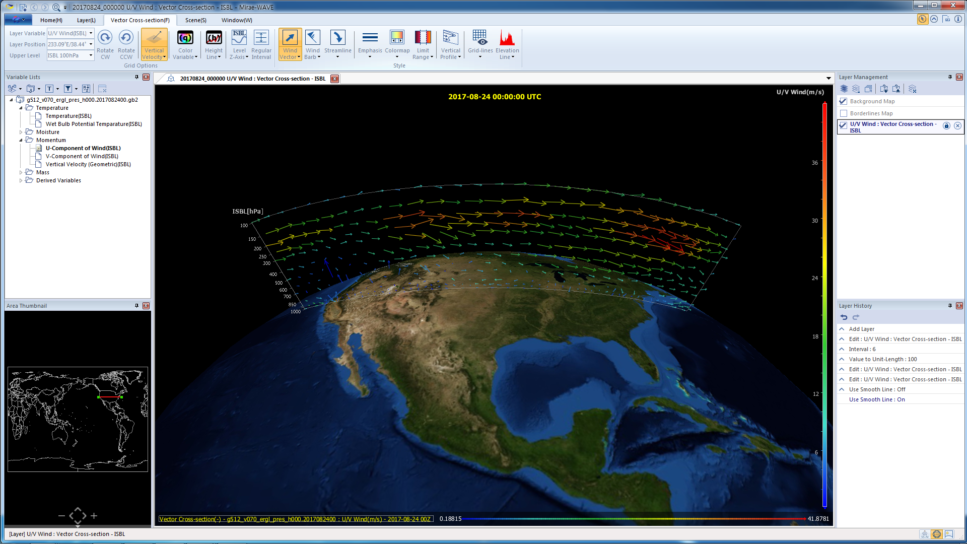
Rendering Pane will immediately display the vertical vector field of wind, and a new layer will be added to the Layers Pane. By default, wind flow will be shown using wind vectors (arrows) at each grid points.
3. Change the visualization style - wind vector vs. wind barbs vs. streamlines (optional).
On Vector Cross-section menu category of Menu Bar, you can select one of the following visualization styles:
- Wind vector : show distribution using arrows with variable length & color
- Wind barbs : show distribution using wind barbs
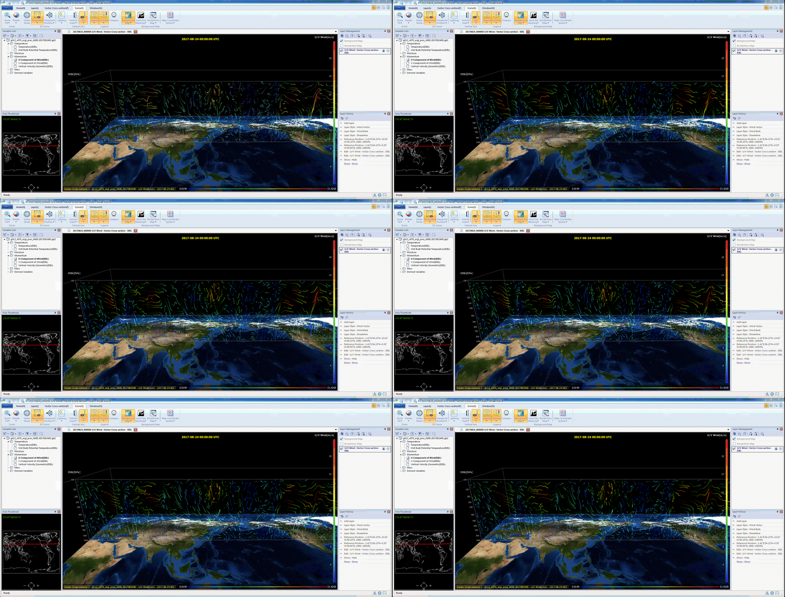
- Streamlines : show distribution using streamlines (optionally with animation)
Each menu button has drop-down submenu, where you can set various options for each visualization style. In particular, streamline style supports animation of the flow, and you can choose animation style as well. Clicking the Streamline menu button starts/pauses the animation. For example, you can choose 'glow' effect in streamline style, so that wind flow is visualized using nice and intuitive animation with colored glowing dots moving at different velocities.
4. Change the settings for color mapping (optional).
Double click the vertical Color Bar on the right-hand side of Rendering Pane. A popup dialog named 'Setup Colormap and Limit Range' will show up, where you can change various options regarding the color mapping.
5. Control the size and location of the plane (optional).
You can control the size and location of the plane by using Rendering Pane only. To do this, you do :
- switch from Globe mode to Map mode,
- double-click one of the corners of the plane, to reveal the control handles,
- drag the control handles to change the size and location of the plane.
You can also change latitude/longitude of the plane, by dragging control handles in the Area Pane.
| Previous Page | Home (Table of Contents) | Next Page |
|---|


